
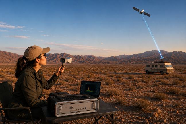
Starlink user terminals transmit high-power, broadband uplink signals in the Ku-band (13.85–14.5 GHz), using phased-array beam steering, frequency-division multiple access (FDMA) and dynamic carrier allocation. These characteristics make passive identification, classification and geolocation of active terminals a technically demanding but operationally significant problem.
From a security and sovereignty perspective, Starlink terminals give adversaries, smugglers and hostile actors highly resilient, high-bandwidth satellite connectivity that bypasses all terrestrial network controls. A single terminal can establish a full-duplex broadband link at any location with sky visibility, which makes the RF uplink signature the only externally observable sign that a terminal is active.
The YOTASYS Y9827A Inceptron Spectrum Analyzer addresses this challenge directly. Using its broadband real-time spectrum analysis (RTSA), CUDA-accelerated IQ signal processing on the embedded NVIDIA Jetson Orin NX and the Y9800A CNN-LSTM signal intelligence platform, YOTASYS has demonstrated passive detection, waveform characterization and the feasibility of preliminary geolocation of Starlink terminal uplink emissions, from a standard compact horn antenna and without any cooperation from the terminal or the Starlink network.
This application note summarizes the measurement approach, the key findings and the path to a production-grade Starlink terminal detection and geolocation capability on the Y9827A platform.
The Y9827A Inceptron Spectrum Analyzer
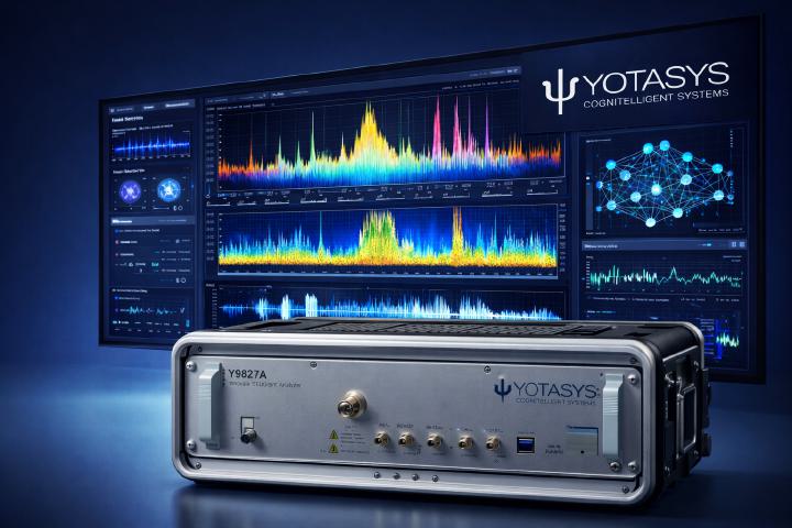
The Y9827A Inceptron is a rack-mounted, full-spectrum RF monitoring instrument designed for continuous, unattended operation in demanding field and infrastructure environments. Its stacked architecture combines the proven RF front end of the Anritsu MS27201A with YOTASYS Inceptron Technology™: an integrated NVIDIA Jetson Orin NX processor running Ubuntu Linux, Node-RED, ONNX inference libraries and the full Y9800A software suite.
At its computational core, the NVIDIA Jetson Orin NX GPU module delivers 157 TOPS (INT8) of AI inference performance in a power-efficient, thermally optimized form factor. This brings cloud-class neural network processing directly to the field sensor, without the latency, bandwidth consumption and data security risks of remote server or cloud-based AI. CNN inference, LSTM anomaly scoring and TDOA cross-correlation all run locally, in under one millisecond per analysis cycle.
For Starlink uplink detection, the Y9827A runs in RTSA mode with OPT-0124 IQ Signal Analysis active, providing:
- A 600 MHz monitoring span that covers the complete Ku-band uplink allocation (13.95–14.55 GHz) in a single sweep, essential for tracking a frequency-hopping terminal across every possible carrier position
- Spectrogram capture with a 200 ms sweep time and 10 kHz RBW, enough to resolve individual frequency hops and the characteristic boot-phase scan pattern
- IQ streaming at 50 MB/s in I16 format to local NVMe storage, providing raw sample data for offline waveform analysis and CNN classifier training
- An RTSA density display (persistence mode) that shows intermittent, slot-based uplink carriers, which may be invisible on a standard swept spectrum display
A simple user interface
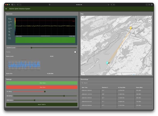
The Starlink uplink detection system is controlled through a simple graphical user interface that opens in any web browser on a connected PC, laptop or tablet.
The display shows a map with the GPS position of the Y9827A and the beam direction of the detected Starlink user terminal, the spectrum of the signal, and a time graph of the detected power level. Operation starts and stops at the press of a button, and every Starlink detection is listed in a table for historical direction reporting.
The user interface can easily be adapted to specific needs, such as storage in a local database, automatic report generation or alarms to third-party systems.
TDOA geolocation of Starlink terminals
Passive geolocation of an active Starlink terminal uses the same TDOA architecture as the Y9827A’s ground-based RF emitter localization. Two or more Y9827A units at separate locations capture simultaneous IQ recordings of the Starlink uplink, synchronized via GPS 1PPS timing. The 150 MHz signal bandwidth and 200 MSPS IQ sampling provide sub-nanosecond timing resolution, which translates into meter-level range differences between nodes.
The boot-phase scan window is an especially favorable TDOA opportunity: for 20 to 30 seconds the terminal sweeps predictably across the full band, giving the multi-receiver array a stationary, high-SNR signal to correlate. During active uplink operation, TDOA correlation must track the hopping carrier across multiple dwell periods, which calls for a wide-span receiver and spectrogram-based time-frequency fingerprinting rather than simple power detection.
For single-receiver or narrowband scenarios, Power-of-Arrival (POA) geolocation provides a complementary estimate with 50–500 m accuracy. The Y9827A platform uses a minimum-variance hybrid fusion architecture that adaptively combines TDOA and POA in real time, as a function of signal bandwidth, synchronization quality and measured SNR.
AI signal classification: CNN-based recognition
Both Starlink uplink signal classes are part of the Y9800A CNN and LSTM classifier training pipeline as distinct labeled categories. The boot-phase scan pattern and the wide, flat-PSD active carrier are spectrally unique compared with every signal class previously in the Y9800A database (LoRa, Sigfox, BLE, Zigbee), which allows reliable discrimination with minimal false alarms.
The CNN processes time-frequency spectrogram representations of the captured IQ data, identifying modulation characteristics, spectral shape and temporal patterns. The LSTM layer adds anomaly scoring based on the learned pattern of life of the monitored Ku-band spectrum: a terminal that activates at an unexpected time or location is flagged even before the CNN classification completes. Custom CNN models for Starlink detection can be trained with the YOTASYS Y9900A service from operator-specific IQ capture datasets.